PMCHY

PMCHY
The Dragging Equipment Detector at State Line, KY

Thursday, August 27, 2020

Construction Update #12 - Operating Software & Upper Staging Yard

Caroute

NOTE:  If you don't have any interest is operations or you are currently using a system with good results you may want to skip down to the layout construction update section below.  If you are considering the use of two sided waybells with four destinations and a car card or another computer program, I suggest you take a look at CAROUTE (www.decapodsystems.com). The program is written in visual basic for Windows based PC's and costs $67.00 plus $3.00 for shipping.  The system works as advertised and the owner of Decapod System, Jim Botsko, provides excellent customer support.  When you need help or have a question, he actually answers the phone and returns emails!

What follows is not a detailed set of "how to" instructions for the installation of the CAROUTE software.  Those instructions are included with the software.  It does however illustrate how one of several available software applications can be implemented on a model railroad. 


Planned Railroad Routing "CAROUTE" from Decapod Systems


CAROUTE is similar, in concept, to the long standing two sided, four destination, waybill and car card system used by many modelers.  As a result, this section may be useful to those who are planning to use that system.  CAROUTE does however offers several advantages over the two sided, four destination waybill and car card system and in my opinion is a preferable solution.

  1. CAROUTE is fully automated and easily edited.
  2. CAROUTE generates a customizable switch lists for each train.  There are no cumbersome waybills and car card to deal with.
  3. CAROUTE will also generate a switch list for one or more industries/yards
  4. CAROUTE allows for up to 20 different destinations on a single waybill.
  5. CAROUTE automatically assigns each car to the appropriate train.
  6. CAROUTE includes a data analyzer and several other tools to fine tune the program.
  7. Your operators won't take home a pile of car cards by mistake when the operating session is over. (I did that once)
CAROUTE requires four different data files in order to generate a switch list.  For a large railroad like mine, this requires a significant amount of time.  I suggest building the files in the following sequence.
  1. Town File
  2. Industry File
  3. Car File
  4. Train File 
Once these are set up, they can be added to the Main Menu/Setup File.  The Setup file will automatically load the four data files each time you start the program.  The set up file also incudes links the data file editor, a switch list generator, and a data analyzer.
In order to load the data files, some preliminary work will make the process easier.  I started with a operational schematic based upon my track plan:
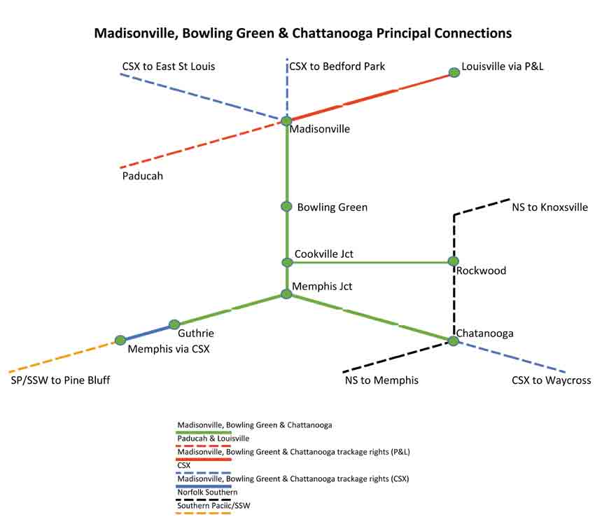


At this point, it should be noted that I only model the portion of the railroad from a point west of Bowling Green to just beyond Cookeville Junction to include a short section of the line to Rockwood.  The rest of the MBG&C is represented by staging,  In the diagram above, the MBG&C is shown by a solid green lines with trackage rights to Louisville over the Paducah & Louisville between Madisonville and Louisville (solid red line) and trackage rights to Memphis over the CSX between Guthrie and Memphis (solid blue line)

The MBG&C, much like the present day Montana Rail Link, is dependent upon overhead traffic.  In the Montana Rail Link's case it's the BNSF providing the overhead traffic. With the MBG&C it's CSX.  As a result, lots of CSX power and equipment are present.  3 trains a day, in each direction, represent this business; one in each direction between Louisville and Memphis and two in each direction between Madisonville and Chattanooga.  With the exception of auto parts for the GM assembly plant at Plum Springs and TOFC for the South Kentucky pig ramp in Smith Grove, these trains are limited to swapping blocks as necessary at Preston Miller Yard in Bowling Green.

Two other trains work the entire length of the line.  There is a general merchandise freight in each direction between Madisonville and Chattanooga and a long distance local/turn between Madisonville and Rockwood.  In addition there are three locals and a yard job centered around Bowling Green.  These trains will be expanded upon in the "Train File" section.


The Town File


The Town File is the simplist of the four files.  While the MBG&C is a north/south operation the CAROUTE software is set up for east to west,  The towns in staging are highlighted in red. They are listed east to west and are entered into the Town File in the same order.

  1. Chattanooga (CSX/NS Interchange)
  2. Crockett
  3. Memphis (SP/SSW Interchange
  4. Memphis Jct
  5. Rockwood (NS Interchange)
  6. Cookeville
  7. Grundy
  8. Coalmont
  9. Westmoreland
  10. State Line
  11. Preston Miller (Bowling Green Yard)
  12. Bowling Green
  13. West Bowling Green
  14. Smith Grove (South Kentucky/Bowling Green TOFC Ramp)
  15. Plum Springs (Bowling Green GM Assembly Plant)
  16. Madisonville (CSX/Paducah & Louisville Interchange)
Here is a sample of the data imput screen for the Town File.  Data entry points, for all four files, are alway shown in white and in all but one case should never be left blank. There are only two significant data points on this form; the name of the "Town" and the "Print code".  The print code is only useful if you want to print a switch list for all trains servicing the industries in that town.  If you want the switch list you would enter a 1 in the "Print Code" box and list the train numbers in the column on the right.  These can be added after the Train File is created.  All of the fields can be edited at a later date.  This process is outlined in the CAROUTE system manual.


Always save the file before returning to the Main Menu.


The Industry File


The Industry File is next.  Industries are always a subset of a town; they can be listed as a industry name, spur, yard, interchange, destination, or anything else for that matter.  The program logic uses the number associated with a industry, not the name.  The same is true for Towns, Cars and Trains.  I made a list of all my industries, again from east to west before I started my data entry.  I'm not going to list my entire Industry File but here is a sample for Chattanooga:

1. Chattanooga (Staging)
  1. NS De Butts Yard
  2. CSX Waycross/Jacsonville
  3. CSX Waycross/Tampa
  4. CSX Atlanta Montgomery
All the industries (interchanges) could be combined but that would require a lot of shuffling around of cars in staging between operating sessions.  The program always assigns cars to the first available train that serves a destination/industry so it may route a car into staging on one train and out on another.  I didn't want that, especially on the upper level 80" above the floor.  Using the 4 different industries (interchanges) insure that trains always come out of staging the same way they went in and any block swapping is done at Preston Miller Yard in Bowling Green.

Here is a sample of the data imput screen for the Industry File.


Note:  A situation may occur where the program will try a send a car to a industry that is already full.  In that case, the program will route the car to the nearest industry with Yard code 1.  On my railroad, the various tracks in Preston Miller Yard are the only industries that have the Yard Code 1. The Industry Files for the town of Preston Miller Yard include the following:
  1. Local
  2. East Bound
  3. East Bound Shorts
  4. West Bound
  5. West Bound Shorts
During the next operating session, the program will make another attempt to ship the car to the original destination.  If this happens repeatably, then the industry capacity is to small or there are to many cars on the layout with that destination.

The town of Preston Miller Yard should also be given the Print Code 1.  Then when the program generates switch lists, it will include one for Preston Miller Yard.  The resulting switch list can be used by the Preston Miller yard crew or yardmaster to help expedite the flow of cars in and out of the yard.  The Car File sample in the next sections includes routing through the town of Preston Miller Yard.

Always save the file before returning to the Main Menu.


The Car File


Here is where things get really interesting.  In order to facilitate this process, I took every piece of rolling stock off the layout and built the Car File car by car, industry by industry.  Each time I added a car to the Car File, it was placed on the layout at the appropriate location.   On my railroad, it  generally takes 4 cars to service a single spot industry during every operating session.  For example, Graham Packing in Bowling Green receives raw materials in 50' XM boxcars.  RBOX 10824 is one of 4 cars assigned and its waybill includes the following destinations:
  1. Graham Packaging
  2. Preston Miller Yard-East Bound
  3. CSX Atlanta/Montgomery
  4. Preston Miller Yard-Local
When I was setting up the layout, I placed RBOX 10824 on the inbound local track in Preston Miller Yard; industry 19, waybill Step 4.  During the next operating session, RBOX 10824 will be forwarded to Graham Packaging (Industry 33).  Additional destinations for ROBS 10824, up to 20, can be added at any time.  Destinations can also be edited or deleted at any time.  The Load Status is the status of the car entering the destination for that step of the waybill, 1 for load, 0 for empty.  Based upon this file, ROBX 1824 will arrive, loaded, at Graham Packaging every 4th operating session.

Here is an sample for the data input screen for the Car File


Always save the file before returning to the Main Menu.


The Train File


I find that developing the train files is more fun than work and a lot of different combinations can get the job done.  In fact, you can develop more that one Train File and change things up from time to time.  Again, the files are easily edited and the system will let you know if a car can't be moved because there isn't a train assigned to switch a particular industry.  Here is an example of the data input file for the Smith Grove Local.  The Smith Grove Local switches all the industries west of Bowling Green.  Note that the train originates and terminates at Gemco Yard.


Power assigned to the Smith Grove Local lays over at the Gemco Yard Office.


The case for Train Symbols


The MBG&C uses alpha numeric train symbols.  I think train symbols are one aspect of operations that many models discount or don't use at all.  Symbols give substance and depth to a train and a sense of reality to the layout.  They tell where the train came from, where it is going, it's purpose, and how it should be handled.   The trains symbols used on the MBG&C are based upon those used by the Southern Pacific prior to 1985.  The first group of two letters is the origin and the second group of two letters is the destination.  The last letter is the type of train.  For example the Memphis to Louisville SP run through carry's the symbol MFLOP (Memphis to Louisville Perishables).  The symbol tells us something about the train.  The MFLOP is a high priority freight with a block of reefers (Colton Block) coming out of California on SP's LAMFT.   The train will probably have big burly SP Tunnel Motors up front that will have to be swapped out for a brace of Paducah & Louisville GP-10's at Preston Miller Yard in Bowling Green.

The "Colton Block" passing through Bowling Green on the MFLOP (Memphis to Louisville Perishables).


My friend, Kurt Boyd, gave me theses "Blue Box" Athearn kits.  I assembled and weathered them in one evening and had them on the layout the next morning. Intermountain wheel sets, Kade #58 Couplers, an extra once of weight, and some weathering turned these inexpensive kits into perfectly good, in my opinion, layout quality models.

So now, if you see a couple of SP tunnel motors up front followed by a block of 57' PFE/SPFE reefers making track speed on the MBG&C, you'll know it's the "hot" MFLOP.  If you're the Preston Miller Yardmaster, you won't want to risk the wrath of the Terminal Superintendent by delaying the MFLOP.  And, if you are the crew assigned to the MFLOP you won't waist the dispatcher's time by asking to hold at Coalmont so you can scurry over to the mine's company store for a cup of coffee or a ice cold Mountain Dew.


Train types on the MBG&C

A    Auto Parts
K    Chemical
D    Drag
F    Forwarder
J    Juice Concentrate
L    Local
P    Perishable
T    Trailers/Containers (TOFC)
Y    General Merchandise

Origins/Destinations


BG   Bowling Green, KY
BE    Bedford Park, IL (CSX)
CH   Chattanooga, TN (CSX, NS)
ES    East St Louis, IL (CSX)
JA    Jacksonville, FL (CSX)
LO    Louisville, KY (CSX)
MA    Madisonville, KY (CSX, P&L)
MF    Memphis, TN (SP)
PB    Pine Bluff, AR (SP)
PS    Plum Springs, KY
RO   Rockwood, KY (NS)
TA    Tampa, FL (CSX)
WA   Waycross, GA


Switch Lists


So....  Now that all the work is done its time to print out the switchlists; go to the main menu and press SWITCH LIST and then press MAKE SWITCH LIST,   The program will ask you for a date or ID number for the switch list and then press OK.  At this point you have three options:
  1. Preview Switch Lists 
  2. Print Switch Lists
  3. Output Switch List to File
Since I like to simplify and add  "Special Instructions" to my switch lists I normally preview and then output the Switch List to a file.  Then I load that file into Word, make any changes, and print out the switch list.  You can also print out the Beginning Status (car locations), the Final Status and errors and warnings. Once you are satisfied, you can press Return and then Update Files and you will be ready for the next operating system.  If you press Continue instead of Update Files, you will be taken back to the main menu and the system will not be updated.

Finally, creating the switch lists requires a complex inter-related set of data to work properly.  This generally means your data will require some fine tuning after the initial data entry.  I'm not done fine tuning my switch lists so a sample will have to wait for a future update.


CAROUTE can handle up to a 200 towns, 300 industries, 100 trains, and 1500 cars.  You might want to give it a try.


Finishing off the Upper Level Staging Yard


The track and wiring on the main part of the layout is all down and tested at this point.  As a result I am just finishing the upper staging yard and have started the bench work for the lower level. Originally, I planned to have the lower level staging yard on a swing gate in front of the garage door.  A couple of weeks ago, I changed my mind.  I concluded that keeping 6 tracks in alignment over a wide range of temperatures and changes in humidity probably wouldn't work.  Eventually Smith Grove will be located were the red toolbox is sitting.  The South Kentucky TOFC ramp and bulk transfer facility will be located in Smith Grove along with Bowling Green Metal Fabricators.  Trace Diecast was also supposed to be in Smith Grove but I have decided to replace it with Univar Solutions, a chemical ingrediant and solutions provider (tank cars).


Here is the entrance to the upper staging yard.  The far track, next to the backdrop, is the eastbound main.  The track in the foreground is the westbound main.  There are four double ended yard tracks inbetween the two mains.  If you include the east and westbound tracks for staging purposes, there are five tracks capable of holding at least three six axle diesels, 20+ cars and a caboose.  There is one shorter track capable of holding two six axle diesels, 14 cars and a caboose.  The turnouts are controlled by Tortoise switch machines.  At some point, I would like them to be dispatcher controlled.  In the meantime, they will be controlled by a small panel at Crockett.


The six tracks run down the west wall of the room and duck into the dispatchers office through a hole in the wall.  The track here is Peco Code 83.


A view from the dispatcher side.  Here, the eastbound main is on the far left.  It loops around the dispatchers office and becomes the west bound main as it ducks back through the hole in the wall..  The radius around the loop is 34"


And finally, here is a view of the dispatchers office from just outside the door.  The bench work for the lower level stub in staging yard is in front of the window.  A couple of the lower level staging yard will duck through the near wall, to the left of the doorway, and continue another 6 feet above my work desk.


Roster Additions


Two additional locomotives have been added to the fleet.  Both were purchased with pre-installed Tsunami2 decoders; both have working rooftop beacons. some light weathering (MIG Panel Line Wash) and came equipped with Kadee couplers.  All I did was install a TCS KA2 Keep Alive and reprogram the speed curve, momentum, and volume.  Both are Master Series Atlas GP-38's.  These are the first two locomotives on the layout in the Y2 paint scheme.


Finally, if you would like to be notified when a new post is added, click on the "Follow" button at the top of the page or send me your email address at sdepolo@outlook.com and I will add your address to the list.  If you would like to be taken off the existing list, please let me know that too.


Friday, July 24, 2020

Construction Update #11 - More Locomotive, A Company Town & Upper Level Staging

Roster Additions


Five locomotives were added to the fleet over the last week or so. C&O #8774 is a Atlas Master Series B30-7.  It got the standard upgrades to include a Tsunami2 sound decoder, a TCS Keep Alive, Kadee #58 scale couplers and some moderate weathering.  CSX #7224 is a Atlas Master Series U-30C that got the same treatment but it has yet to be weathered.


Chessie #4340 and CSX #3103 are Both late run Atlas Master Series locomotives  Both got the standard upgrades; Tsunami2 sound decoders, TCS Keep Alives, and Kadee #58 Couplers.  #4340 got light weathering and #3103 has yet to be weathered.  Both locomotive we set up for and got 21 pin Tsunami2 decoders; a first for me.  The keep alive leads were soldered directly to the Atlas mother boards per instructions provided by Soundtraxx.  Soldering the keep alives to the mother board turned out to be much easier than I originally thought.  The GP40-2 also got upgraded with "Natural Light" LED's from Evans Design.  The Evans Design LED's come in several sizes ranging from tiny to small and are pre-wired with resistors/rectifiers for use with 7-19 volts.  I protected the leads where they attach to the LED with clear fingernail polish.  The tiny leads are lacquer coated and should be handled with care.  


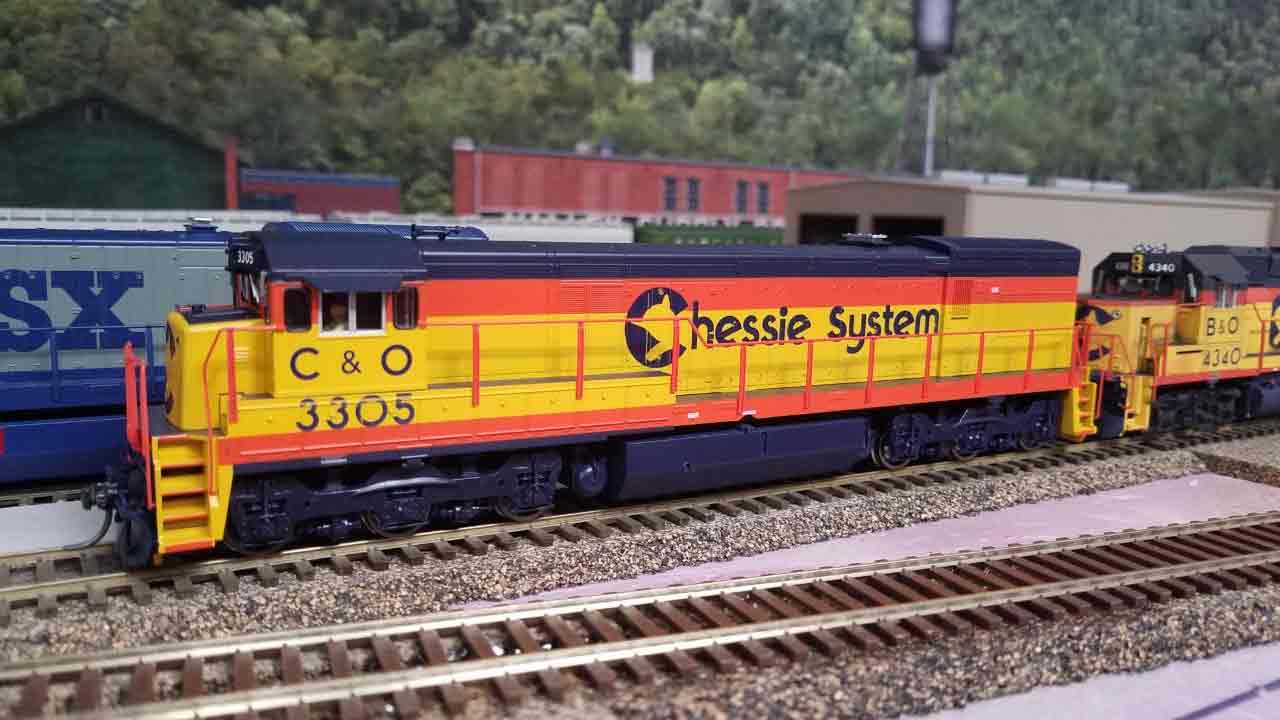
The fifth locomotive added to the fleet was another Atlas Master Series U-30C.  Chessie #3305 got the standard upgrades and is another locomotive waiting to be weathered.


For those of you who are interested, here is a copy of the photograph sent to me by Josh Levine at Soundtraxx.  I suspect, but have not verified, these solder points will work on any 21 pin motherboard regardless of who manufactured the model or the decoder.


Grundy - A company town


As I have mentioned in previous updates, the Union Mining Company tipple and company town of Grundy are planned for the area directly above the helix.  I finally got back to Lowe's for a couple of sheets of plywood so I decided to start working on this area even though I was short a turnout.   I used part of a sheet for the upper level return loop and the rest at Grundy.  The upper section of the helix will wind around the left side Grundy and duck into a tunnel above the c-clamp on the left hand side.


The tipple will be located at the end of a box canyon with the company town located on a hillside to the right.  That/s the Coalmont Branch on wall and extending to the right above the door in the background.  The branch will terminate in the corner to the right of the door.


All the track work and electrical installed.  Currently, I planning on two locals working this area.  The first will originate here at Grundy, collect loads from the local tipples and load outs, and run down the hill to Preston Miller Yard in Bowling Green.  On the way back it will work Grundy and continue up the Coalmont Branch.  The second local will work the same locations only in reverse.  It will originate in Coalmont, work its way down the hill to Preston Miller Yard in Bowling Green and return to and terminate in Grundy.  The Union Mining Company tipple will ship about 8-12 cars a day.  The house track holding the power for the Mountain Local.  The spur is equipped with an on-off switch to kill the power.


The Upper Level Staging Yard


The upper level staging yard is situated just beyond the summit at Crockett. The upper level staging consists of a large reverse loop with 4 long double ended staging tracks.  The train shown in the photo is on the westbound main.  The eastbound main is on the far side of the tracks.  The tracks here will run down a shallow valley before slipping behind a low ridge line and into staging.  The train is located at the current end of track.


Peco code 83 track and #8 turnouts are being used for the upper staging tracks.  The eastbound main and staging yard throat are up against the wall.  The west bound main is in the right foreground.


Here's what the throat looks like from the underside


Here's another view of the upper level staging yard throat.  The yard will extend to the left, across the top of the garage door and into the dispatchers office.  The lower level stub end staging yard will be on the lower level.  These tracks will hold about 25 cars, three locomotives, and a caboose.


Here's a photo of the dispatchers office.  The bench work for the lower level staging yard is on the left.  The upper level staging and reverse loop will run along the perimeter of the room about 80" above the floor.  This room is about 6' x 8', just large enough for the reverse loop's turn back curve.


And finally, here's a photo of  my spray booth.  It's been sitting on the floor, out of use, for the last 19 years.  It is equipped with lights and a explosion proof fan that vents to the outside.


Wednesday, July 8, 2020

Layout Tour

Significant progress has been made over the past 3 months so I thought I would use a post for a layout tour.  The main line is fully functional from the entrance to the lower staging yard to the entrance of the upper staging yard and reverse loop. 

The western end of line is in Madisonville. Kentucky (staging)   The Madisonville staging yard will be along the west wall of the room.  At the east end of the yard, the mainline will make a 90 degree right turn and head down then north wall.  Smith Grove, KY and West Bowling Green occupy the north wall.  The General Motors Bowling Green assembly plant is located in Smith Grove.  The plant is supported by a small yard  (GEMCO) and yard office.  The Smith Grove Local originates here daily except Sundays.

(1)  Power for the Smith Grove Local is tied up at the GEMCO yard office.  That's the GM plant in the background.  GM makes Corvettes at the Bowling Green assembly plant.  As I understand, the finished Corvettes are trucked to a loading point outside of Kentucky before being shipped by rail or truck to dealers. 


(2) We're going to follow the MC1 (Madisonville Chattanooga Expediter) around the layout.  The MC1 originates in Bedford Park, IL (CSX) and it consists primarily of auto parts, empty Tropicana reefers on their way back to Florida, and TOFC.  Eventually there will be a hotel, gas station, and a couple of fast food resturants here in the background.  For now... Use your imagination.  The WP box car will be set out in the GEMCO yard (left foreground),


(3) Further down the north wall is Hills Pet Nutrition in West Bowling Green.  Hills Pet Nutrition is one of Bowling Green's largest employers.  The acutal Hills looks nothing like the model.  Hills receives grain products and corn syrup by rail, and ships out pet food.  MC1 is about to swing to the right and enter Preston Miller Yard in Bowling Green.


(4)  MC1 is passing through Preston Miller Yard in Bowling Green.  Located on the east wall of the room, the yard is about 26 feet long. MC1 doesn't normally stom at PM.  Additional yard tracks will eventually occupy the space in the left foreground.  I have plenty of flex but finding Micro Engineering Code 70 #6 turnouts has been difficult.


(5)  Southern Kentucky Feed & Grain is at the east end of the yard along with the MBG&C engine facility.  Most of my locomotives are Atlas and all my locomotives are equipped with Soundtraxx Tsunami2 sound decoders and TCS KA1 or KA2 current keepers.  Hot frogs and stalls are a thing of the past with current keepers.   Just about all my turnouts have drops to install frog juicers but with current keepers in the locomotives I have come to the conclusion that hot frogs are a waste of time and money.


(6)  Today's MC1 has a ex SCL extended vision caboose on the bottom end.  I should probably change the number for CSX but I don't get to excited about those kind of details.  Those pig flats are destined for Jacksonville, Florida.


(7)  Another curve to the right, this time 180 degrees, brings MC1 down the center peninsula and over Romanza Creek (Previously No Name Creek).  The peninsula is about 22' long so it nice long run of single track.


(8) Once across Romanza Creek, the track swing around the end of the penisula and enters Westmoreland.  Westmoreland is the site of the CEMEX redi-mix plant, Amerigas, a team track and the base of a 2.2% grade (helix) to the upper level.


(9)  The helix was a cause for concern when I was planning the layout.  The plan required that it be in the narrowest part of the room which meant that a wider radius on the helix meant a narrower aisle somewhere else.  I ended up with a 30" radius on about a 2.25% grade.  As it turned out, the radius hasn't been a problem.  I have run 30 car trains, including 89' flats, up the helix with all the power on the front end or with helpers cut in ahead of the caboose without a problem.  I do wish I had cut the roadbed a little wider.  Side clearances are tight for long cars. 


(10) Grundy is at the top of the helix.  The grade levels out here to facilitate the switching of several load-outs (coal).  Eventually a large tipple and company town will be located withing the loop directly behind the Tropicana reefers.  Here at West Grundy there will be a control point and as a result one of the less than a dozen powered turnouts on the layout.  If you have read my previous posts, you already know that I plan to use the Atlas "plug and play" Signal System.


(11) Grundy is a coal mining town.  The Grayson McClure loadout is in the foreground and the spur above the locomotives leads to Dunleary Coal.  This area is directly above Westmoreland on the lower level. 


(12)  East of Grundy, MC1 is back on the 2.25% ruling grade.  The manifest sitting at Crockett (summit) is at the end of double track, sitting on the westbound main, waiting for MC1.  Romanza Creek and bridge are directly below this scene.


(13)  MC1 is approaching the loop around to the summit.  The two hoppers seen above the locomotives are sitting at the Claywell Mining loadout on the Coalmont Branch.  The branch crosses over the mainline and into a tunnel {staging} representing the rest of the branch.  Currently the branch is a single track but I have been thinking about adding a second one.  Theoretically, there are three customers on the branch; two lumber companies and the Spillman Mining Company.


(14) MC1 has just crossed the west switch at Crockett on the eastbound main. Lighting is a problem on the upper level that I haven't quite figured out.  At this point, MC1 is about 20 inches from the ceiling and the florescent lights are creating hot spots.


(15) And finally, MC1 reaches the summit at Crockett.   MC1 is already on the reverse loop that will include the main track and 4 staging tracks.  At Crockett, there is a crossover between the east and west mains to facilitate the dropping off of helpers, a house track, and the junction with the Coalmont Branch.  A small depot and tool/speeder shed will be located in the flat area in the left foreground.  There will be another shed and telephone booth down at the cross over. 


(16)  MC1 has cleared the west switch at Grundy and the 8000 is creeping down the westbound main in anticipation of a clear signal at West Grundy.  This train is NS28, a Chattanooga to Preston Miller Yard (Bowling Green) manifest with traffic off the Norfolk Southern.
t

Finally, if you would like to be notified when a new post is added, click on the "Follow" button at the top of the page or send me your email address at sdepolo@outlook.com and I will add your address to the list.  If you would like to be taken off the existing list, please let me know that too.


Saturday, June 27, 2020

Construction Update #10 - Scenery Base on the Upper Level

Painters Paper Scenery Base


Over the last month or so, I have been looking at alternatives to traditional methods of creating scenery.  I needed something to protect the lower level, that was lightweight, quick and easy, and relatively inexpensive.  On the Sn3 layout a solid pink foam base covered by a layer of plaster cloth worked great.  But, the cost associated with using all that pink foam was something I really needed to avoid this time around.  One of the "you tubers" (railfan220), as my grandson Adam calls those of us who spend way to much time looking at video/s, came up with the idea of using painter's paper over cardboard webbing to create a scenery base.  As it turned out, I used one sheet of 1" pink foam, 5 or 6 cardboard boxes, and one roll of painters paper to cover the entire second level.  Total cost, less than $50.00 including the glue.  Eventually, I will probably cover the painters paper with a layer of plaster cloth and a layer of earth colored latex house paint before adding ground cover, vegetation, trees, and other details.
 
Here is what it looks like when its done.  Not bad, huh?


The process starts with drawing a ridge line on the backdrop with a black felt pin.  Then pink foam  profile supports, spaced about 6-8" apart are glued in place using hot glue.  Next, cardboard strips are glued in place along the ridge line.  These were cut, across the corrugations, using a flat bed paper cutter.


The cardboard strips are then bent down, roughly following the contour of foam profile boards, and glued to the edge of the roadbed.  The lower level is done the same way; first gluing to the side of the roadbed and then to the side of the lower roadbed. 


The webbing is next.  Since this picture was taken, several months ago, I have found that gluing a cardboard strip along the top of the webbing, next to the backdrop, is a good idea.  It helps to have a smooth service on the upper edge when applying the painters paper.


Painters paper is available in most hardware stores.  I bought this roll at my local Ace Hardware.  It comes in various sizes and it was marked "for latex paints".  This roll cost about $7.00.


Unlike the webbing, I found that it was easier to start at the bottom.  I wadded up the painters paper and then folded over the lower side by about a 1/4".  A bead of carpenters glue was put down along the edge of the roadbed and the painters paper was pressed into the glue.


I normally let the glue set up for two or three hours before trimming off the top, running a bead of glue down the sides of the painters paper and along the top of the webbing.  The painters paper is then stretched out and pressed into place.


The summit at Crockett, before:


After:


It's surprising how sturdy the end result is and now I don't have to worry about anything dropping through the bench work and damaging something on the lower level.  I spread the work over a week or so but the entire upper level could probably have done in a couple of weekends.

Note:  Since I started this process, I have run across a couple of other examples of this type of scenery base.  Several skipped the pink foam profile boards in favor of just using the cardboard webbing.  Unless you plan to use multiple layers of plaster cloth, over the painters paper, I don't recommend omitting the pink foam profile boards.  I tried it and the end result was easily deformed and not nearly as strong.

On the work desk


I am slowly back dating the layout into the mid to late 1980's.  As a result, I picked up a couple of  Chessie units off ebay.   Both are my preferred Atlas "Master Series" locomotives, a GP40-2 and a B30-7.  The GP40-2 was a real bargain but the previous owner had really butchered the cab by trying to attach the sun shades and wind deflectors with ACC.  By the time I got all the ACC cleaned off the cab, It needed a repaint.  It also had a 21 pin adapter for a sound deoder which was all fine and dandy until I discovered there was no easy way to install a "current keeper" along with the new 21 pin Tsunami2 decoder.  As it turns out, the "current keeper" can be soldered onto the Atlas motherboard or the Tsunami2 (Soundtraxx technical support) but the work requires a tiny soldering iron and some serious magnification.  I've ordered the soldering iron from Nngineering so I guess I will give it a try.  Since the GP40-2's were the last locomotives purchased by Chessie, before the CSX merger, it has been lightly weathered.

The B30-7 is a simpler project.  It arrived in perfect condition so all it really needed was some moderate weathering and the installation of  the sound system.  I usually sacrifice the rear lighting in order to install the largest speaker and enclosure possible and preserve the weight.  It will get a PNP Tsunami2, a TCS KA1 or KA2 current keeper, and scale #58 couplers.  Both locomotives should be ready for service in the next couple of weeks.


Finally, if you would like to be notified when a new post is added, click on the "Follow" button at the top of the page or send me your email address at sdepolo@outlook.com and I will add your address to the list.