The American Model Builders 85' Wood Roundhouse
Note: If you have no interest in building a wood laser kit, then you may want to skip this post and the upcoming Part 2.
By the mid 1970's, the roundhouse was pretty much a thing of the past. The few that remained were getting minimal us since modern replacements were better suited for the maintenance and repair of diesels. Some railroads, like the Western Pacific in Stockton, California, used two stalls of their old roundhouse for prepping and painting locomotives and several other stalls for light servicing and repair of yard and local power. One time, I even saw the WP's business car, The Feather River, occupying one of the stalls. The "garden tracks", tracks radiating out from the turntable outside the roundhouse, were used for storing locomotives awaiting heavy repairs or retirement. This is how I plan to use the old wood roundhouse standing behind the "new" servicing facility at Bowling Green.
Day 1 - Thursday June 4 (2 Hours)
As I indicated in the last post, I choose the AMB version of a standard wood Missouri Pacific roundhouse for the engine facility at Preston Miller Yard in Bowling Green. It comes in a 2, 4 and 6 stall version and it can be expanded to just about any number of stalls with the "add on" stall kits. I chose AMB #172, the 4 stall version. American Model Builders has been in the laser kit business for a long time and there kits show it. The materials are first rate, the kits are well engineered and they go together with little or no fiddling for fit. And, while I don't recommend this as a "first" laser kit, it is not a difficult build.
What follows is not a detailed set of instructions on how to build this or any other laser cut wood kit. It does, however, cover some of the things I have learned to ease construction, eliminate or minimize mistakes, and end up with a quality model.
The kit includes detailed instructions with two sealed bags of parts; one for the outer stalls and one for inner stalls. I read through the instructions twice and decided to start with the outer stalls. I familiarized myself with the parts by laying them out on my desk and comparing them to the parts diagram included with the instructions. There are several different types of laser cut materials included in the kit. I separated them by type before going on to the next step.

I always give the laser cut parts a light sanding along the edges and than an initial stain coat of Silverwood. The Silverwood gives any exposed wood a weathered look. I will probably paint the exterior oxide red with dark green or brown trim. I prefer solvent type paints. Water based acrylic paints cause the the wood to swell and warp. The interior will be given a light coat of white, with some of the raw wood showing through to represent white wash. With the exception of the peel & stick components, stain and paint both sides of the wood (helps prevent warping).
I have heard complaints about peel & stick parts not holding over time. On my old Sn3 layout, I had several kits built with peel & stick parts and over a decade or more never had a problem. I suspect the solvents in the paints and stains could be a problem. As a result, I am very careful when staining or painting the peel & stick components. The stain and paint should be applied sparingly and kept away from the adhesive.
Once they are stained, but before they are dry, I place them in between 2 sheets of copy paper and then add a book on top. This will keep the parts from warping as they dry.
Here are all the parts, stacked between books for drying. I leave them overnight before starting assembly. If you are going to brush paint the model, you may want to paint the components and repeat the drying process before starting assembly. Since I going to use an air brush to paint the model, I prefer to wait and paint some of the parts as sub-assemblies.
Day 2 - Friday June 5 (3 Hours)
I use Aleen's Original Tacky Cement for assembling wood kits. It tacks up fast but can be worked for about 10 minutes. If the cement ends up where you don't want it, let it sit for a couple of minutes and it will peel away from the wood without leaving a residue. An Xacto knife with a old #11 blade, with a broken tip, is the perfect tool for peeling off the excess glue. The glue cures in about 30 minutes depending upon temperature & humidity.
Some people use gap filling ACC to build wood structures. I don't like it on wood kits except for reinforcing the inside of some corner joints. It tends to soak into and fill the porous wood grain and leave a sheen once it sets.
Alignment is very important with this or any other kit when it comes to building up the side walls. I used a machinist square to make sure the first "post" was square with the edge of the siding and then used an old Xacto knife to scrape away any excess glue.
The interior bracing consists of three sections of laser cut peel & stick material. Care should be taken in removing the wall sections from the carrier. The studs are fragile and break easily. Sand the bottom side so the wall sections can be applied perfectly square with the bottom of the siding. Care should also be taken when removing the backing from the double sided adhesive tape. Start from the bottom. I got underneath the tape on one of the sections and pulled some of it loose.
Use a square to make sure the bottom is perfectly aligned with the siding material. If it isn't square, any discrepancies are exaggerated as you add additional sections,
Here are the completed wall sections ready for paint.
At this point in the construction, the instructions suggest that you build all four rear walls at the same time. I missed this little tidbit of info when I originally read through the instructions and only built 2. Then I had to open the second sealed package and stain another set of parts before I could go on. Here are the first 2.
As I indicated above, most prototype roundhouse interiors were originally coated with whitewash to improve the lighting. But, over time, the upper portion of the walls and the rafters would turn black from locomotive exhaust. I sprayed the lower portion of the walls with a thin coat of flat white. Then, rather than paint the upper sections and rafters a darker color, I decided to leave those areas alone in order to highlight the interior details.
The outside of the walls were painted with Floquil Southern Railway Box Car Red followed by a dry brushing of Floquil Rail Brown. The swirl marks in the wood, visible under my work light, disappear under normal lighting.
The peel & stick doors and windows parts were airbrushed a dark brown. The paint was applied in multiple light coats to prevent the paint from seeping into the adhesive tape. Both the walls and the peel & stick window and doors were set aside to cure overnight.
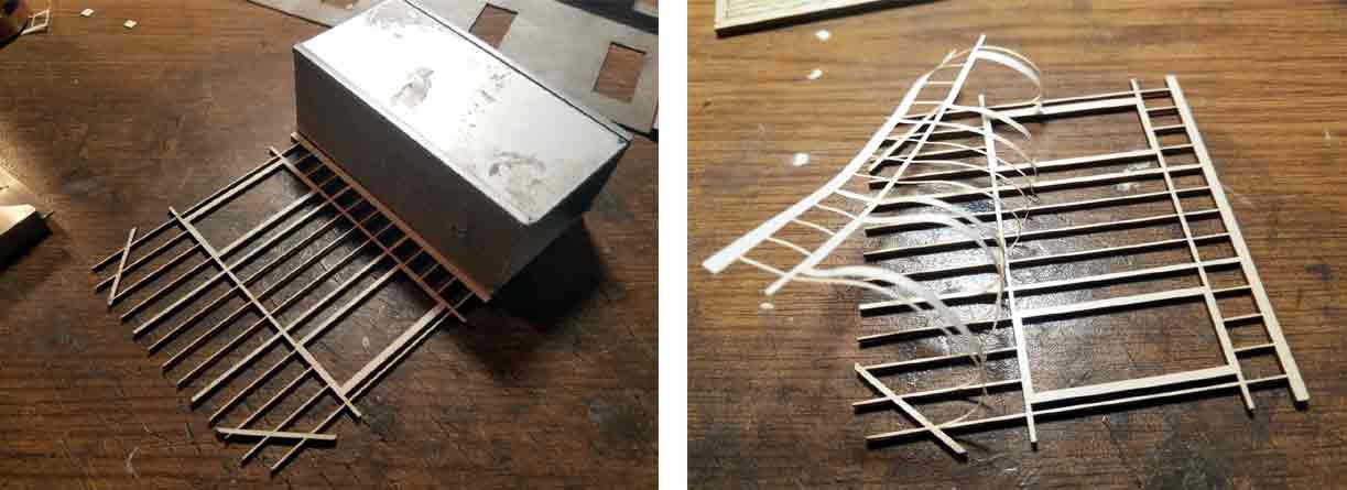
I finished off my modeling session by creating a template for laying out the turntable leads and roundhouse on 4 sheets of copy paper. I assembled the laser cut floors and traced the stalls onto the paper. I marked the track centers on the outline of the roundhouse and drew in the converging center lines. Later, when I install the roundhouse, I will simply glue the template onto the layout and install the track over it.
Day 3 - Saturday June 5 (6.5 Hours)
At this point I deviated from the instructions. They call for assembly of the walls before installing the doors and windows. I have found that it is much easier to install the doors and windows, if possible, before the walls are assembled. Several years ago, I spent some time on the Big Island of Hawaii where I built a Sn3 two stall engine house. Since it would be nearly impossible to carry the completed model home on the airplane, I assembled, painted and weathered all of the sub assemblies (walls and roof sections) and took them home "flat" in the original box. Once I got home, it took me about an hour to assemble the finished wall assemblies and roof. Since then, I have always painted, weathered and installed the windows and doors, whenever possible, before I assemble the walls.
There are a lot of windows to assemble, 52 to be exact, and I find the assembly time consuming and tedious. Each requires up to 5 separate pieces to assemble. I assembled all of the doors and windows in one modeling session. Once they were in installed, I put a small dab of glue on each inside corner to insure they stayed in place over time.
One of the finished side walls and two of the back walls are shown in the following photo. I choose to leave one of the doors open. I trimmed away the door frame, on one side, and glued the door directly to the wall.
I installed all of the doors and windows on the side and rear walls. The engine house doors and windows will have to wait until after the side and back walls are glued together. Before calling it a day, I glued both side walls to their respective back wall section.
Day 4 - Sunday June 6 (5 Hours)
Picking up where I left off, I added the two middle back walls. I used machinist squares to make sure the walls were perpendicular to the base. Some minor sanding was required, on the last back wall section to improve the fit The same technique was used to install the front walls/doors.
Building up the front wall sections (4) was not difficult but it was time consuming. All the doors and windows were assembled first. Then I started with one of the center stalls fronts. The assembly consisted of the 2 outer posts, two windows, the header for above the engine house doors, the small strip that runs between the windows and the top of the header and the base. I started by mounting the windows and center strip to the header. Building around the windows kept things square. Then I added the corner posts and the base. Once the glue was dry, I glued the base to the foundation and added the roof support beam. The engine house doors will be added later.
At this point, I decided to block off the stall on the left. I did it for two reasons. First, I've seen this done on several old roundhouses and I thought it would add some interest and second, I ruined one of the roundhouse doors while trying to laminate two pieces of peel & stick material together. AMB offered to send me replacement parts but I decided not to wait. I used a piece of scribed wood and a door from Pikestuff to fill in the opening. A MOW truck parked outside the door and a couple of workers standing around should look pretty good.
Once
all 4 walls were in place, I started on the roof. It was coming along
nicely until I realized access would be needed, from the top, to install
the track and some interior details. The base of each front wall
section, while needed for stability and alignment, makes it nearly
impossible to install the track and interior details before installing
the roundhouse on the layout or some other base.
As always, if you have a question or comment please send me an email at sdepolo@outlook.com. In addition please feel free to share the Blog with anyone else who may find it of interest.
Part 2 should be posted on or before June 15


